Please note that this ESC has a very limited control range. Meanining that it will act almost like but better then a switch.
What you need:
| Servo |
| Mosfets (see below) |
| 500 ohm Resistor(s) |
MOSFETS
Choose from the following mosfets: IRF530 or IRL2203N.
When using more than one mosfet, use the same type (either IRF530 or IRL2203).
| SPECS. |
|
|
|
| Manufacturer |
|
|
|
| Type |
|
|
|
| ECG Part # |
|
|
|
| Max Current @25°C |
|
|
|
| Max Current @100°C |
|
|
|
| Max Voltage |
|
|
|
| Data Sheets |
|
|
|
* Based on Mosfet by Fairchild Semiconductors. (Varies with manufacturer)
Note: IRL 2203N is a better mosfet for the use here and I highly recommend using it. However IRF 530 is easier to find.
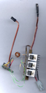
It is strongly suggested that more than one mosfet are used.
MOSFETS are drawn this way for ease of construction.
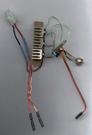
Instructions
Get an old servo where the servo amplifier still works. Cut off and remove the motor from the servo but leave some wire from one of the cables leading to the servo motor. Connect this cable to a 500 ohm resistor. Then connect that to the GATE (G in diagram) of the MOSFET. Find the negative wire of the servo which leads to the receiver, solder some wire onto it and connect that to the SOURCE (S) of the MOSFET and the negative port on the battery for the motor (note: this is not the battery for the receiver). Then connect the DRAIN (D) of the MOSFET to the negative port on the motor. Then connect the positive port of the motor to that of the battery. When using more than one MOSFET, use a seperate resistor for each one (see diagram below).
Schematic diagram showing the ESC with 2 MOSFETS connected in parallel.
Note that there is a seperate resistor for each MOSFET.
Continue to add MOSFETS and resistors as necessary.
|
|
|
|
NOTES
The thick blue lines in the diagram show where thicker cables should be used.
A couple of MOSFETS should be connected together. The more you use the smaller the energy loss. You should also put some heat sinks on the MOSFETS because they tend to heat up during use.
This electronic speed controller is for forward use only which means your model can't go backwards.
There are currently no plans for an ESC with REVERSE and/or BRAKE.
Are you into solar robots. Visit my Solar Robotics Page.